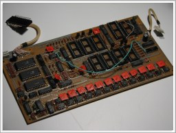
Лель ПСР (Lel' PSR) Rhythm Machine (1989)
Samplerate: 15.625kHz
Waveforms: 12
Waveform format: uncompressed signed 8 bit linear.
Waveform ROM size: 26624 bytes total (7x 2kbyte + 1x 4kbyte + 1x 8kbyte).
System controller: COP402 clone (КР1820ВЕ1А) with 2kbytes of program
and 2kbytes preset pattern ROM; 6kbyte battery backed user pattern+song RAM
Sound module: Pure logic and counters, parallel DAC multiplexed for all
waves, analog s&h for every wave. Panning and level preset via
resistors.
Here are decoded lossless conversions of all sample ROMs for your sampling enjoyment: WAVs in ZIP
Regarding sounds and general information, you can check the awesome Ruskeys.Net website.
Also you can hear Лель ПСР drums in one my song - check MUSIC, listen to "Aerobika 1985"
 |
|
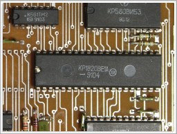 | Upper (system controller) board CPU - КР1820ВЕ1А - a COP402 clone. Current attemt at firmware disassembly. Not yet commented - help me with it: Lower bank program: disassembly in TXT Upper bank program: disassembly in TXT |
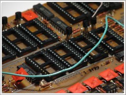
 | Sound Module board with desoldered ROMs and added sockets. |
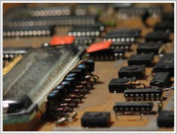 | VFD display ИВЛ1-8/13 from then-popular soviet calculators (Электроника МК-56 for example). |
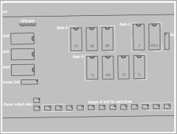
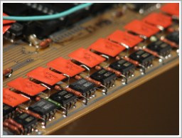 | Sample and hold circuits for every drum, with level and pan set via two neighboring resistors. This is where you can connect sends from every drum output or even make an attached level, pan and send "mixing" board. Check the sound module board sketch (below) for exact drum instrument locations. |
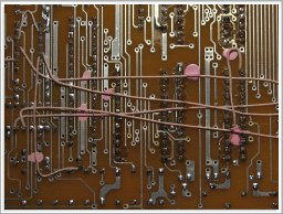 | Truckload of patch wires that originally were there from factory. Both boards obviously had a million problems with just about everything. :-) |
Power supply
External power supply is 12V DC center positive, shell negative. Unit feeds on about 300-500mA.
Внешний блок питания Лели ПСР (по крайней мере - моей) должен быть 12V постоянного тока, центр - плюс. Жрёт не очень много, где-то 300-500mA.
Internal power supply board produces (in a clumsy way) several voltages for the Controller board and Sound module. Internal power supply board will not work if any of the boards (or their interconnection) has been detached. This odd behavior is due to a weird design: 250kHz ALE output from CPU is passed on to sound module board and then passed to power supply to operate voltage multipliers.
Sound module (sample playback) board
Waveform ROMs on the sound module board are divided into three banks. Each bank has a common sample position counter, therefore independent multiple sample triggering (within one bank) is not possible.
WaveROM bank-A holds six 1kbyte samples, stored on three 27C16.
WaveROM bank-B holds four 2kbyte samples, stored on four 27C16.
WaveROM bank-C consists of an 8kbyte ride cymbal (on 27C64) and a 4kbyte open hihat (two piggybacked 27C16; should have been one 27C32).
One parallel digital to analog converter is used for all voices by multiplexing. It's output is then sampled and held by discrete analog components.
Afterwards, s&h output gets buffered and sent via two resistors into left and right mixbus.
There is one additional digital to analog converter that I call here "Volume DAC"
It creates a reference current for the waveform DAC. It is not used for "accent" - just the awkward linear volume adjustment, common to all drums.
Sound module board map sketch: (click for larger image)
This sketch currently only shows waverom locations, s&h designations and a few other basic things.
Sound
module control port allows to write three bytewide registers (3x К561ИР6). Port has
D0..D7 data lines (input only), three synchronous latch input signals
and 250kHz master clock input.
Latches are written to using positive pulses.
Samples are triggered by setting respective bit to 1.
Latch0 and Latch1 are used for sample triggering, noisegate and accent bits.
Latch2 is used only for Volume DAC. Only lower 6 bits (bit0..bit5) are connected, bits 6 and 7 are unused.
Latch0 bits7..0: Snare | Bass | x | x | Tom 3 | Tom 2 | Tom 1 | Closed HiHat
Latch1 bits7..0: Rim shot | Cowbell | Accent | x | Clap | Bongo | Open Hihat
Pinout (from left to right, looking on the board as it is seen in picture):
1 - GND
2 - not used
3 - Clock to sound module (250kHz square)
4 - GND
5 - Latch2
6 - Latch1
7 - Latch0
8 - D7
9 - D6
10 - D5
11 - D4
12 - D3
13 - D2
14 - D1
15 - D0
Metronome Click (in realtime record mode) uses Closed Hihat wave, gated very short:
Beat1: 1.43mS
Beat2: 900uS
Beat3: 750uS
Beat4: 600uS
Gate time determines click volume.
Due to a firmware bug, metronome sound is offset by one quarter of a beat. Quite annoying.
Accent
effect is made using analog mux right after stereo mix bus amplifiers
(2x УД608). Analog mux is on the left lower side, chip К561КТ3. Accent
bit (from latch1) gets inverted and bipolarized, and is connected to
pins 6 and 12. Normal volume when +5V, higher "accent" volume when -5V.
Playback multiplex
time slots are each 4uS long and there are 16 of them. Only 12 are used.
Time slot counter is right beside К561КТ3 in the lower left corner of
the board, chip К561ИЕ10. Input clock 250kHz is on pin1. Time slot
number bits TS3..TS0 are on pins 6..3.
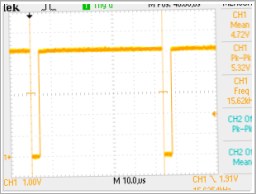 | One active 4uS timeslot. Period 64uS. (click) | 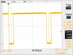 | Two active timeslots. (click) |
Output sample&hold
array is on the lower side of the board. There is one УД608 amplifier
for each drum instrument. You can take individual outputs from pin6 of
every s&h op amp. Levels and pannings (sends to L and R mix bus) are
set via resistors located between op amps. Red rectangular capacitor is
the hold charge storage of the respective s&h.
Refer to the drawing above for instrument s&h locations.
Individual outputs will have no volume accent effect as it is applied after mixing all sounds together.
Controller (control panel) board
Controller board CPU is extremely minimalistic 4bit COP402 with 2kbytes of program ROM and 2kilobytes of pattern ROM. Program ROM is on dedicated bus and uses address latch (К1533ИР23 located right besides "П64" ROM chip) for lower address bits A0..A7. All other chips and Pattern ROM "ТАБ" are on the other bus that is operated using general purpose IO.
CPU receives 4MHz clock and it internally divides it by 16 to make main system clock (used by everything else): 250kHz 50/50 duty cycle square.
Playback beat timing and update/scanning is maintained using classic i8253 timer chip - КР580ИР53. Timer chip generates two fixed rates - 25Hz on OUT0, 4kHz on OUT1 - and one tempo relative on OUT2. OUT2 is quite a nice find -- it is the usual MIDI 24 ticks per quarter note for the selected tempo. It can be used to make ЛЕЛЬ ПСР capable of MIDI Slave Sync. At 120bpm there should be 48Hz 50/50 duty cycle square. At 200bpm there should be 80Hz. You can calculate the required rate by: (bpm/60)*24
There is space for UART (DIP28, i8251) and optocoupler (DIP14 soviet classique) on the controller board for MIDI, but unfortunately firmware does not make any use of it. CPU never reads nor writes anything to/from UART. MIDI button on the panel is not connected (misses a diode) and does not do anything even when diode is installed.
Display driving is very simplified: It can only use 8 of 12 character spaces and only number digits 0-9 can be displayed. No letters, no dashes, no points despite microcomputer control - Thanks to the use of hard 7-segment numeric character decoder chip (К176ИД3).
User pattern+song RAM is made up of three 2kbyte RAM chips (К573РУ10). Each pattern takes ~32bytes, there are 64 user patterns and 8x 225step songs. Battery backup circuit is unreliable and SRAM chip driving has no provisions for safe power off. There is no power brownout detector and no masking of transient errorneous write control signals at power on/off. And, by the way, there is no way of bulk dumping/loading songs and patterns - no tape load/save or midi support. So the user pattern and song feature is just for the time the unit is kept powered on... While it may keep the data from batteries while powered off, it is in no way reliable or reloadable at data loss.
Firmware is comprised of two parts, each exactly 1kbyte. This is due to the fact that CPU cannot address more than 1kbyte, so a large program requires paging / bank switching. Paging system here is made up of a single bit latch. It can be set or reset via software routine to transcend to other page within two cycles. Lower part of the program does key readout and display mode logic and sample playback triggering, while upper part does display scanning, pattern position counting etc. There is space for additional 2kbyte program rom and it had some bank switching support.
Here's a quick try at disassembling Лель ПСР firmware:
Lower bank program: disassembly in TXT
Upper bank program: disassembly in TXT
I wrote a straightforward COP402 disassembler for it and it also adds some automatic comments where such could be helpful. Instruction set matches COP402 datasheet and MAME project emulator's one. I don't know of any COP402 assembler as well as any of it's oddities and number formats, so I just used $ for hex and % for binary strings, as well as ; for comments.
After taking a peek at the code and doing visual sanity check you may think that there must be a truckload of mistakes in the disassembler, as jump opcodes, asm lines and comments seem messed up. But no - it's a mistake to do a sanity check on 4-bit weird ass thing like COP402. Yup, jumps are all funked up and different instructions work differently from different address areas.
And yes, a lonely "x" is an official full instruction mnemonic.
If you have programmed on COP400 series please help with commenting the code.
I will also do some execution trace capture and analisys on the actual system just for fun. Results might be helpful in understanding i/o routines, conditions and branches.
Lower bank program is the one located $000..$3ff and upper bank is $400..$7ff.
ROM chips
For
some weird reason, nobody else seemed to have
dumped the roms from this popular soviet drum machine. Or maybe,
somebody had made rom dumps, yet after spending hours desoldering just
didn't want to share them for free. So someone had to do it and
share them with you :)
And finally - here they are!
Twelve ROM chips from a working drum machine, all carefully soldered out one by one.
All 2kbyte DIP24 chips in it are 27c16 compatible, and the 8kbyte one is 27c64 compatible.
BIN and HEX files contain the same data, only file format differs.
CPU_P64: from upper (CPU) board, program rom for COP402 clone - КР1820ВЕ1А.
CPU_TAB: from upper (CPU) board, rhythm patterns and a few other tables.
Waveform
ROM filenames have one or two letters after an underscore, that match
the ones written with paint on the original chips.
SAMPLE_G: Likely meant "Гонг", ride cymbal.
SAMPLE_KK: Likely meant "Каубел" and "Клап", cowbell and clap.
SAMPLE_T: Tom 1-3.
and so on.
Hihat sample spans both H1 and H2 roms.
Refer
to the "sound module board map" picture for ROM chip location
on the pcb. Factory and original design IC position numbers are unknown
due to the lack of any silkscreen print.
Original data dates back to September 21, 1989; "MOSCOW (C) CAM INC."
| IC pos. |
IC type |
IC contents |
Data binary image |
| no silkscreen on pcb. |
27C16 and 27C64 |
Includes
program ROM (П64) for КР1820ВЕ1А, lookup table ROM (ТАБ), as well as
all wave roms (БР, Г, Х1, Х2, ХБ, КК, МБ, Т1, Т2, Т3). |
Get the BIN files |
FAQ in russian - мои ответы на вопросы в форумах/ё-майлах:
> Какой-нибудь Z80 там должОн быть.
Там отечественный клон древнего 4-битного процессора COP402 - КР1820ВЕ1А. Программа 2килобайта + ритмы 2килобайта, хотя тот процессор по прямой может адресовать только 1килобайт.
Дата разработки программы: 21. сентября 1989.года "MOSCOW (C) CAM INC."
(21. сентября 2012 года празднуем 23-летие со дня рождения Лель ПСР!)
Подробная информация и прошивки ПЗУ на английском тут выше.
Надеюсь когда-то нарыть свои древние бумаги и ещё много техинформации выставтиь.
> А у него девайс с "кроватками"..
Эти ПЗУ с обеех плат я сам выпаивал и панельки новенькие покупал и впаивал. Кто-то же со всего бывшего СССР должен был их считать. ;)
Разве чёрыне, красивенькие панельки AMP так легко спутать с советскими страшными голубосинеми кирпичами? :)
> есть два набора пзушек судя по плате и два набора счетчиков .
Три набора - см. рисунок и описание выше.
> И есть только один ЦАП как ни странно
Две штуки ЦАП: Один устанавливает громкость и даёт опору второму - тот сэмплы и проигрывает.
> А почему две части дисассемблиранного кода? Там же, вроде, одна ПЗУ?
Две части так как проц не может адресовать более одного килобайта. В таких случаях исползуют bank switching и программа софтверно переключает высшие адреса ПЗУ (в случае Лель ПСР - А10 и неиспользованное второе ПЗУ) и в тот же миг оказывается в другой части. Для того хитро писать приходится, чтобы такие переходы происходили куда надо и в том месте уже было бы продолжение кода с прошлой части.
> когда выпаивали дорожки не отслоились?
Хитрым аппаратом (паяльник с встроенным электронасосом) выпаевал, всё получилось без особых разрушений. Иными способами не мозахиствовал, так как хорошо знал эти страшные платы с времён АОН и Zx Spectrum. Всё равно занятие была на долгое время, так как ромов уйма, платы мерзкие, миллион проводков (сфоткай, отпаяай и потом обратно всё поставь) итд..
Разпаял я его где-то в 2005 или ранше, мне кажется. А до того (как её достал) всё время хотел для него мод-ромы сделать с барабанами больше по моей электронной линии - как смешную бандуру с колоритным дизайном по рублю..:))
> Если дамп просто пытаться воспроизвести, то фигня получается.
> Он (дамп) что, "зашифрован"?
Да нет - там просто старый трюк с перемкшиванием адресной шины и/или шины данных, для более удобной разводки платы. Там же, где ПЗУшки и есть уже в формате WAV эти ромы с всём сконвертированно-развёрнутым нормально.
Нащёт конкретной пермутации адресной шины и/или шины данных уже не помню.. Но помню, что всё легко понял смотря по битам на цап и счётчиках. Перекодировал всё своими инструментами, которыми также могу вести поиск неизвестных "закруток" шын. Но тут всё просто было. Формат там тоже больше жестяной чем соундбластерской династии, так что как нативный raw 8bit игатся всё равно не будет, нежели только на amiga с сопроцессором paula.
Нашчёт "блокирования" кнопок во время звучания - да нет, там ужасная программа, которая сканирует кнопки в скорости TEMPO.
Возможно играть только квантованно, при том пэды надо нажимать немножко раньше.
На сколько помню, со сканированием клавиш там дела состоят очень некрасиво..
Скорость сканирования зависит от
установленного темпа. Из-за того там был такой бред, что держа темп +/- кнопки
скорость счёта менялась
пропорционально. Разумеется, триггеринг барабанов может происходить только "в ритме"
с внутренним тэмпо. :(
Из за совмещённых трёх счётчиков, он физически не может свободно триггерится не перезапуская все барабаны в конкретной "банке".
Из за безмултиплексного управления ЦАП громкости (там только один регистр, 6 бит), все барабаны всегда звучат на одной громкости. Акцент работает через него - на то и обеденённый.
Звуки содраны с чего-то конкретного прстоклавишного (нашёл ту яамаху но забыл.. хотя те же сэмплы могли быть и в других). Потом в ДР-8 и ДР-9 разбавились другими сэмплами с других ямях аля PSS-790. Звуки, почему-то, сдирались через некачественную аудио запись. Рас ужсдирали, то могли и по прямой из пзушек вытвскивать и конвертироавть.
Игралась она весёло, но на выходе обязятельен был сочный British EQ, компрессор и bpm пинг понг дилей. ;)
Надо поискать в каких то росийских кодер-обществах кого-нить, программившего КР1820ВЕ1А..
> Насколько известно в то время компания Лель не захотела платить за лицензию по миди протоколу, поэтому до самого интерфейса дело не дошло.
> Лично у меня была без миди(только гнезда).А вот приятель имел машинку с миди.
MIDI протокол, поддержка и описания всегда были за дорма. Только если хочешь свои номера sysex иметь, то надо годовой взнос платить.
И даже если надо было бы плотить... всем в СССР и пост-СССР было наплевать на лицензии и начихать на копи-райт. Звуки в лелях то краденные...
Всё это легенды и байки. И "у друга был с миди" - тоже.
Это как легенды времён детства, что если в яйцах "игра на екране" пройти за 999 очков, то "будет показывать диснеевские мультики"... И тоже не редко "друг прошёл и смотрел" байки циркулировали.
Кнопки МИДИ и ПАУЗА не подключены (отсутствуют диоды), и программа вообще не обрабатывает кнопку МИДИ. Если впаять диод, кнопка ПАУЗА как-то в софте обрабатывается, но как - пока не ковырял.
Для MIDI можно установить оптрон и 8251 UART но всё равно процессор лели никогда не читает/пишет из/в порт.
Хотя останки концептов MIDI есть в одном месте - внутрений темп базирован на миди midi tick-ах, и возможно добавить 24 TPQN MIDI clock тактовый выход, и даже вход, если перецарапать дорожку от ВИ53 OUT2, и за место него подавать 24 TPQN такт в процессор.
